
Robots tackle complex geometries in additive manufacturing, 3D cutting and composite layup.
Robots are extending their reach. These multi axis articulators are taking 3D manufacturing and fabrication to new heights, new part designs, greater complexity and production efficiencies. Integrated with systems to extend their reach even further, their flexibility is unmatched.
See how robots virtually defy gravity in additive manufacturing (AM), tackle complex geometries in cutting, and collaborate with humans to improve efficiencies in composite layup. This is the future of 3D.
 Robotic AM Goes Big
In just a few years, robotic additive manufacturing has gained significant ground. From robotic laser cladding and binder jet technology to laser hot-wire AM processes, now robots are going big with help from age-old welding processes.
3D printing is already a multi billion-dollar industry, with much of the activity focused on building prototypes or small parts made from plastics and polymers. For metal parts, one additive process garnering lots of attention is robotic wire arc additive manufacturing (WAAM).
In robotic WAAM, a robot equipped with a gas metal arc welding (GMAW) torch melts wire into successive weld beads to create a free form 3D shape layer by layer. The Lincoln Electric Company has made a big-time investment in this technology and the resulting parts are formidable in size and scope.
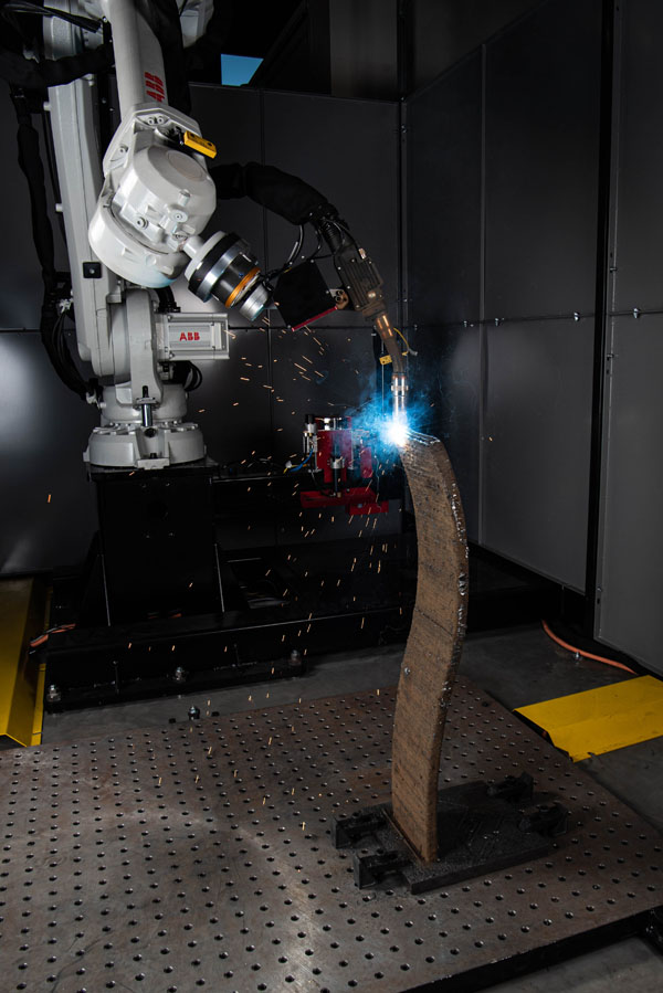
Down the street from the company’s Cleveland-based headquarters, the Lincoln Electric Additive Solutions division houses 18 production WAAM systems and one laser hot-wire system. Combining robotics and advanced motion control with welding technology refined over a century, the Additive Solutions team produces large-format metal 3D printed parts for the aerospace, automotive, marine, mining, construction and oil & gas industries.
Following a major acquisition, Lincoln Electric also has the mega-machining capabilities to deliver large-scale finished metal parts and tooling.
“We’re focused on large-scale parts measured in feet and meters, not millimeters or fractions of an inch,” says Mark Douglass, Business Development Manager for Lincoln Electric Additive Solutions. “Some of these parts weigh hundreds and even thousands of pounds.”
See how 3D printing robots go big, at home.
Perfectly Positioned for Flexibility
Constrained only by a robot’s reach, metal parts and tooling can span up to 6 feet. But the flexibility of robot systems allows them to go bigger still.
“The big benefit of robotics is greater flexibility – flexibility in the number of axes you can use and control, and accessibility of the torch to different areas of the part – especially when used in conjunction with positioners,” says Douglass.“When you use a six-axis articulated robot arm with a positioner, in our case we use sky hook positioners, they give you a lot of flexibility and accessibility that you would not have otherwise.”
Robotics is easily scalable to larger parts. “It’s straightforward to put a robot on rails. You can also put a robot on a movable pedestal.”
You can extend the robot’s reach simply by moving a robot to different positions on a rail, or robot transport unit (RTU), in conjunction with a positioner to rotate or manipulate the part’s position for great accessibility with the welding torch.
Positioners also reduce or eliminate the need for support structures. Douglass explains:
“Particularly when you’re depositing molten metal, if you try to extend outward from the edge of the part (called overhang), you can only go so far until gravity takes a hold of the liquid metal, overcomes the surface tension, and it starts to droop. The beauty of using a robot with a positioner is you can tilt or even rotate the part as you begin building up the overhang features. You rotate the part so the material you’ve already put down becomes the support structure for the next layer.”
He says the trick is doing it in such a way that gravity doesn’t work against you. Support structures need to be removed after the additive process, so reducing them reduces waste and the added cost of removal.
Coordinating motion between the robot and positioners is critical to the 3D printing process. The planning software and system controls play integral roles.
Software with an Edge
The process starts with a 3D CAD model of the part to be produced. Software is used to virtually slice the part into layers. The more complex the part, the more slices or layers.
In the WAAM process, those layers will consist of multiple weld beads of metal.The software must determine the optimal tool path for the welding torch, which varies with each build layer.
Lincoln Electric Additive Solutions uses their own proprietary Sculpt Print™ OS CAD-to-path software to slice the CAD model, determine the ideal tool paths for material deposition, and optimize process parameters for each layer. The software also programs the robot and coordinates movements between the robot and positioners.
“It requires not just coordinated, complex motion control to manipulate the robot and positioners, it’s also understanding the physics of the process, being able to model it properly in the software,” says Douglass. “There are so many variables that go into it. If you’re stacking multiple beads in a layer and then hundreds or thousands of layers, it gets complex pretty quickly.”
Collision avoidance becomes even more critical. With additive processes, the part is constantly growing and changing. Early in the process there may be little to no material in a particular area and the robot is free to move in that space. Two hours later, that same space could be occupied by several new layers of the part.The software must take those changes into account and program the robot accordingly, so it does not crash into the developing part.
Total Control, Rapid Turnaround
Control plays a big role in the success of these processes. Lincoln Electric takes control of the entire process from start to finish.
“Because we make our own wire and power supplies, we know the arc, the welding, the metallurgy and the process,” says Douglass. “We’re able to bring it all together, to get parts right the first time with high quality.”
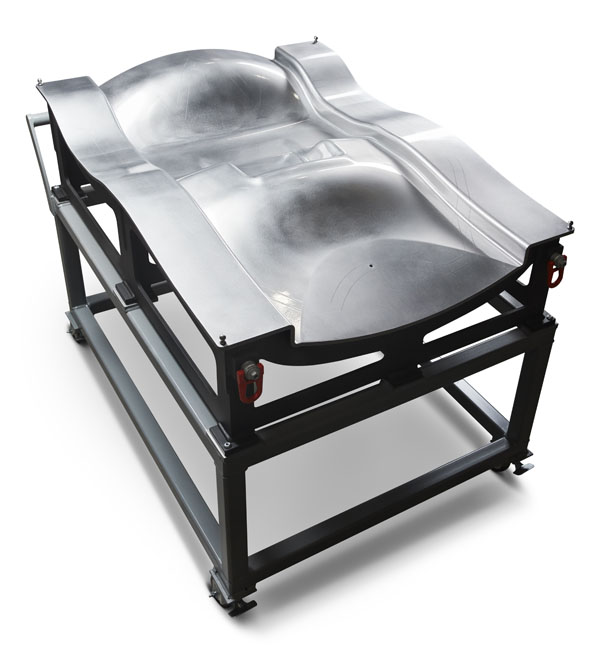
Those parts range from layup molds for making carbon fiber parts for aerospace, or molds for the tool & die industry, to functional metal prototypes, replacement parts for heavy industry, and complex parts like propellers for ships. Materials include steel, stainless steel, bronze, aluminum and nickel alloys.
“One of the primary advantages our customers appreciate about additive is the turnaround time, which is typically much faster than castings,” says Douglass.“With castings, a lot of engineering and design work goes into figuring out how to pour the metal, where the metal is solidifying inside the part and reducing thickness variability. All sorts of things go into figuring out a mold design. Then you may have to do a couple iterations before you’re happy with it.
“With additive, we have so much control over the process. Just as important, we can print a part that is hundreds if not thousands of pounds in a matter of weeks that would take months for a casting.We’ve won some of these aerospace tooling jobs specifically because our delivery times on the completed tools were weeks faster than traditional fabrication methods.”
Douglass says they run 24/7, which is typical for any additive process. The process runs continuously until the part is finished. The time it takes to 3D print a part depends on its shape and complexity.Using robotic WAAM, this large aerospace tool took just 6 days to print.
In another application, a 500-pound impeller took about a week to 3D print. Because the blades on the impeller were hollow, that made the build process more complex.
“One of the benefits of additive is you can make components that you wouldn’t be able to make otherwise. Good luck casting a hollow-blade impeller,” says Douglass.
Creating hollow structures reduces the weight of the part, the amount of material needed to print it, and therefore the print time, which reduces production costs. Additive also allows for integrating internal structures like cooling channels in dies.
“Delivering on quality is harder than it looks, especially when you’re operating multiple systems in a 24/7 production environment,” says Douglass. “To do it right the first time with high quality is not an easy task. We worked very hard to get to this point.”
Looking ahead, he anticipates more hybrid cells. After all, robots are born multi taskers. With advanced tool changers, a robot could 3D print and finish a part in the same cell. One of the limitations for WAAM is the lack of standards or certifications for wire-based additive processes. As standards are written and adopted, Douglass expects the market to explode in the next 5 years.
Meanwhile in the Netherlands,robots are shaping our additive future.
Robotic WAAM for Spare Parts
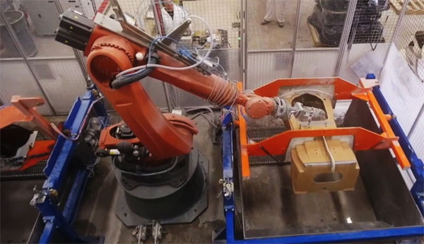
Renowned for using robots to 3D print a steel bridge, an Amsterdam-based startup now spans the industrial landscape. Metal 3D printing company MX3D is using robotic additive manufacturing to demonstrate the advantages of 3D printing large-scale metal parts, including replacement parts for heavy industry.
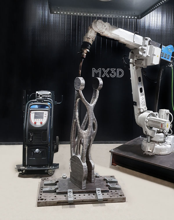
In cooperation with ABB Robotics, this robot arm was 3D printed in stainless steel using an advanced version of MX3D’s WAAM technology and MetalX LCAD-to-print software to build complex geometries.With continuous 24/7 production, the 73kg re engineered part can be printed in 4 days.Following precision machining of the component connections, the part was reinstalled on the robot to demonstrate functionality.
Watch the entire process take shape.
“Compared to powder-based technologies, robotic WAAM enables faster, larger, more flexible and more affordable 3D metal printing,” says René Backx, Chief Commercial Officer at MX3D.“This allows for rapid, automated production of large-scale parts that normally require extensive tooling and overseas production, causing long lead times and limited customization options.”
Rapid metal 3D printing with industrial robots could allow heavy equipment manufacturers and sellers to manufacture spare parts in-house, even robot arms.
3D Cutting Outside the Box
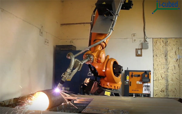
Back on the other side of the pond, the port city of Hamilton in southeastern Ontario is home to Canada’s largest steel and metals manufacturing industry. Just 12 miles outside city center is the community of Stoney Creek, where I-Cubed Industry Innovators Inc. is known for their robotic 3D cutting expertise.
Established in 2008, the automaton integrator shares facilities with sister company South port Thermal Components Inc., a custom component manufacturer with expertise in water jet cutting technology. Another division sells extruded aluminum products under the brand name Item.I‑Cubed not only builds robotic systems for clients, but also uses them daily in their South port job shop.
“We have large six-axis robots cutting with multiple water jet heads all day long. Robots with spindles on them, with chainsaws on them, robots with plasma cutting heads,” says Jeff Martel, Applications Manager at I-Cubed. “We use industrial robots to do relatively high-accuracy operations.”
With a production “showroom” next door, I-Cubed specializes in the design, integration and offline programming of robotic cutting systems.In addition to robotic material removal, the integrator builds robot systems for material handling, machine tending and inspection. They also use robots to do 3D printing of concrete structures for the building industry.
Robotic Versatility for Water jet, Plasma
Similar to robotic additive processes, the flexibility of robots in conjunction with rails and part positioners plays a significant role in the size and scope of cutting applications.
“In our shop, we have a KUKA robot that can reach nearly 10 feet out and then it’s on a 6‑meter rail, so it’s got an envelope basically 10 by 24 feet long, which is huge for the industry,” says Jeff Martel. “If you were to buy a machine tool with an envelope that large, granted it would be a little more accurate, but it would be about 10 times the price. Robotics allows you to make very large envelope machinery for more affordable prices.”
Robots also allow you to easily change the spindle head for waterjet, printing or other processes, making cells much more versatile.
Watch 3D cutting robots on the job performing waterjet, plasma cutting, part-to-tool machining and multiaxis milling in metal, foam, wood and composites.
Waterjet cutting uses a high-pressure stream of water, sometimes mixed with abrasives in abrasive waterjet, to slice through a variety of materials, including food, fabrics, metals, stone, plastics, glass and composites. Robotic waterjet brings six degrees of freedom to the cutting process, which can slice through steel and titanium alloy several inches thick at various angles.
“We do a lot of aircraft shroud rims for jet engines (with abrasive water jet),” says Jeff Martel. “We use a six-axis robot with the shroud mounted to a seventh-axis rotary located over a water jet tank to catch the stream.”
I-Cubed uses water jet robots for 3D cutting everything from aerospace components and automotive carpeting to hot tubs.
3D Milling and Offline Programming
Programming multiaxis3D cutting can get complicated. To coordinate the movements of the robot along with the movements of part positioners, I-Cubed uses robot offline programming (OLP) software. OLP software eliminates the need for tedious point-by-point robot programming.
Watch this “warrior” come to life with I-Cubed’s robotic milling cell programmed with Robot master OLP software.
I-Cubed also built a robotic system that is helping bring century-old stone carvings back to life on Canada’s Parliament Hill. Time has not been kind to the ornate Gothic Revival features and many limestone sculptures of the capital buildings. Technology is poised to save them.
Once the sculptures are fully digitized from 3D models, a robot mills the figures from stone. Then an artisan sculptor adds the fine details by hand.Hundreds of interior and exterior stone sculptures will have been renewed with high-tech tools and automation by the time this colossal heritage restoration is complete.
Robotic 3D manufacturing is infiltrating every sector of industry. As composites continue to be coveted for their high strength-to-weight ratio, industry is looking for ways to automate composite component fabrication.
3D Composite Layup
Researchers at the University of Southern California (USC) are working with aerospace OEMs to bring robots, artificial intelligence, advanced motion control and sensing technology together to automate the layup process for fabricating composite aero structures.
Popular for their structural strength and lighter weight compared to metallic materials, composites contribute to better fuel efficiency and reduced airplane emissions. The fabrication process involves stacking several layers of carbon fiber prepreg material onto a contoured surface to create a laminate. The laminate is then cured using heat and pressure to make a composite component.
The laborious process of stacking layer upon layer of prepreg material on a mold, or tool, is called layup. Two main types of automated layup processes, automated fiber placement (AFP) and automated tape layup (ATL), use robotics or other forms of automationto lay up narrow tapes or fibers onto the mold. Check out this AFP robot at NASA.
For 3D composite components with more complex geometries, the layup process typically involves large sheets of carbon fiber prepreg material. Sheet layup is dependent on manual labor, requiring a pair of workers, one to perform the dexterous work of conforming the tacky sheet to the mold while the other worker helps support and position the sheet. To combat the ergonomic challenges of hand layup and increase throughput, OEMs are looking for ways to automate the process.Researchers and robots at USC are lending a hand.
During previous research in conjunction with Lockheed Martin and United Technologies Research Center, the USC team designed a fully automated cell with three robots handling sheet layup on a relatively simple, curved mold. See the cell in action.
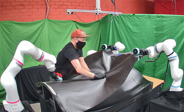
In more recent research with Boeing and Rensselaer Polytechnic Institute (RPI), the USC teamdesigned a human-robot collaborative cell. In this setup, two robots hold the sheet while a human and a third robot work together to conform the sheet to the mold, including manipulating the sheet into tight concave regions and other geometrical complexities of the mold.Watch the collaboration.
Both projects were funded by the ARM Institute with the objective of automating composite sheet layup with robotic assistants working alongside humans to enable larger-scale production and more ergonomic working conditions for humans.
Human-Robot Collaboration
As a manual process, human workers find sheet layup challenging both from an ergonomic perspective, but also in terms of maintaining consistent quality from layer to layer. Some composite structures could require up to 20 sheets. Each side of the sheet is tacky, so it’s important to support the sheet above the mold and not release it prematurely. Humans usually work in tandem supporting, draping and conforming the sheet to the underlying tool shape.
Amid the global pandemic, concern over social distancing adds another challenge when manual layup requires a pair of humans working closely together.
Robots address all these concerns, but also come with their own set of challenges. In both the fully automated robot layup cell and the human-robot collaborative cell, coordination between the robots is critical. The lead researcher explains.
“For someone to write all the code for each of those robot motions, it would take forever for the program to be created,” says Satyandra K. Gupta, Ph.D., Smith International Professor of Mechanical Engineering and Computer Science in the Viterbi School of Engineering at USC. “That’s where AI comes in. The robots can program themselves.”
Gupta’s team wrote all the software that enables the robots to adapt to uncertainties during the layup process and ask humans for assistance when needed. This is thanks in part to advances in computing power, which makes running AI in real-time possible.
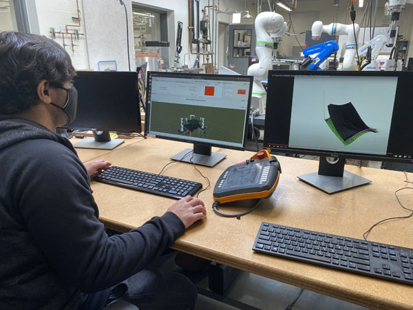
Advances in sensors and their new-found affordability allow USC to put five depth cameras on their robots.“You can imagine as the physical robot cell is running, in the computer it’s running a digital twin,” says Gupta. “That way we can see what the simulation is predicting should be happening in the cell and what is actually happening in the cell, which is being measured by the sensors.”
The computer vision is primarily for tracking the composite sheet position.But the properties of the sheet material change as the process progresses. Once the sheet is removed from the freezer where it’s stored, the clock starts ticking. Ambient temperature and humidity influence how the sheet material behaves.
Humans are very good at adapting to these changes, because we can feel the tackiness of the sheet. Robots find that challenging.
“Right now,the sheet layer process is designed to work in temperatures that are comfortable to humans,” explains Gupta. “The speed of these processes is consistent with humans. But robots don’t have to worry about temperature or speeds comfortable for humans.”
The sheet must be brought to an elevated temperature to properly conform to the mold. Human workers heat the sheet with a heat gun, working locally in a small area at a time, and then use a rolling tool to conform the sheet to the mold. This heat-and-roll process must be repeated for each section of the sheet and each layer.
But robots don’t sweat. In the future, the fully automated process could run at elevated temperatures where the sheet is more compliant.
“Process speeds could be three to four times faster,” says Gupta. “In the future, when the process itself has been made more friendly for robots, then you will see huge gains.”
Gupta and the project’s industry partners are excited for the technology’s potential.“We have demonstrated that it can be done. Now it’s largely about maturing the technology, having the right user interfaces and the right kind of reliability.Had it not been for the pandemic and aerospace taking a big hit, I’m pretty sure people would have started building their own internal cells. Demand is down right now, so there’s some reluctance to invest in new technology. But everybody is convinced this is the future.”
In a manufacturing world with growing customization and part complexity, robotics lends itself well to high-mix, low-volume applications that are becoming the norm rather than the exception. With intuitive software, AI and advanced sensors, complex geometries are no match for unprecedented control. Robots are the future of 3D. For more flexibility, more freedom.
About the Author :

Ms. Tanya M. Anandan
Contributing Editor – A3 Robotics
Formerly Robotics Industries Association (RIA)
Association for Advancing Automation (A3)
![]()
Ms. Tanya M. Anandan is a freelance tech writer and a contributing editor for the Association for Advancing Automation (A3), the leading global automation trade association of the robotics, machine vision, motion control and industrial AI industries.
LinkedIn : www.linkedin.com/in/tanyamanan
This article originally appeared on the A3 website.


, tackle complex geometries in cutting, and collaborate with humans to)