

An Industrial Engineer’s Advice to Small and Medium-sized Manufacturers (SMM) Investing in Industry 4.0
A Note from the Author
This article focuses only on machine shops. Compared to other HMLV (high-mix low-volume) manufacturers who have been my clients, they are the most progressive thinkers and adopters of Industry 4.0 technology. That is the reason why I have several success stories to back up the recommendations I offer in this article and discuss in depth in my book!
What is Job Shop Lean?
This article assumes that the reader is familiar with Job Shop Lean, my approach to adapt the Principles of Lean for a job shop, regardless of its size or industry sector. The following articles will give the interested reader a sufficient background on the many differences between Job Shop Lean™ and Lean:
 1. Adapting Lean for High-Mix Low-Volume Manufacturing Facilities
2. A Quick-Start Approach for Implementing Lean in Job Shops
3. Remaster the Five Principles of Lean Manufacturing
Laying the Foundations for Adoption of Industry 4.0 by SMM (SME)
The Toyota Production System was designed for assembly plants that produce 100’s of 1000’s of automobiles.
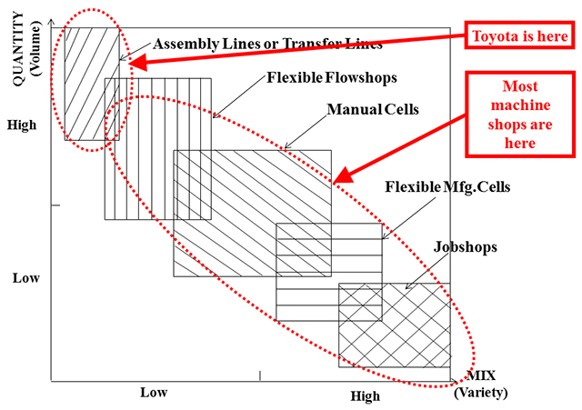
Figure 1 compares a machine shop and an assembly plant using two key characteristics of any production system – Production Quantity and Product Mix. Clearly, an assembly plant focuses on low-mix high-volume (LMHV) production whereas a machine shop focuses on high-mix low-volume (HMLV) production. Lean is based completely on the Toyota Production System. So a machine shop cannot expect to realize the complete benefits of Lean by using just tools that are primarily suited for an assembly factory.
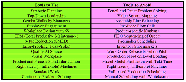
Today, nearly every machine shop has benefitted from implementing one or more of the Lean tools listed in the left-hand column of Table 1. In contrast, the Lean tools in the right-hand column of Table 1 are ineffective or inapplicable in any machine shop. They cannot handle the complexity of a Make-To-Order high-mix low-volume machine shop, especially if it is a job shop.
 Unfortunately, Industry 4.0 lacks the capability to help an SME design a production system that suits their HMLV shop floor. Failing which any software or technology that the SME invests in will never achieve the performance goals that the SME wishes to achieve!
Table 1 Lean Tools that a Machine Shop Should Use and Avoid
Strategies to Lay the Foundations for Industry 4.0
This article discusses several viable practices, software and technology to replace the Lean tools listed in the right-hand column of Table 1.
Segment the product mix:
Most machine shops choose to make a diverse range of products that differ in their annual production volume, demand pattern and margin. Based on these three business attributes, segment the products into two segments – (Runners + Repeaters) and (Strangers). For parts in the (Runners + Repeaters) segment, batch sizes will tend to be medium or large with many parts having LTA (Long Term Agreements). In contrast, for parts in the (Strangers) segment, batch sizes will tend to be small because orders for these parts tend to be Hot/Rush one-off’s, repair, prototype, start-of-lifecycle or end-of-lifecycle. For each of these two segments, different order fulfillment strategies, rules for CRM (Customer Relationship Management), business practices, etc. need to be used. This practice of a shop-within-a-shop is on display at every hospital, which is essentially a health care job shop. It has an Emergency Department that operates like a stand-alone hospital in order to achieve the short lead times that are essential to give rapid customized care to a large number of patients who do not need to be admitted to the main (and much larger) hospital.
Split the shop into two shops:
In Shop #1, produce orders for parts/products that are in the (Runners + Repeaters) segment of the product mix. In Shop #2, produce orders for parts/products that are in the (Strangers) segment of the product mix. Set up Shop #2 to operate as a QTS (Quick Turnaround Shop) with AM (Additive Manufacturing) machines, flexible automation, multi-tasking machines, machining centers with pallet-changers, etc. that can produce any part in any quantity in a single setup! In fact, even the skill levels of the employees in the two shops ought to be different! The employees in Shop #1 will be those who prefer production runs of mature parts; whereas the employees in Shop #2 will be those who prefer the challenges of one-off manufacture of complex parts and have an intrinsic desire to master new technology.
Rationalize the product mix at the end of every year:
At the end of each year, eliminate those products that are losing money aka “Cats and Dogs”. As the GM of one machine shop quipped to me years ago, “We are happy to send our difficult parts, and sometimes our difficult customers too, to our competitors. It does not hurt our business if the production efficiencies and profit margins of our competitors get damaged by the customers we fire!”
If the shop currently has a Process Layout, change it immediately!
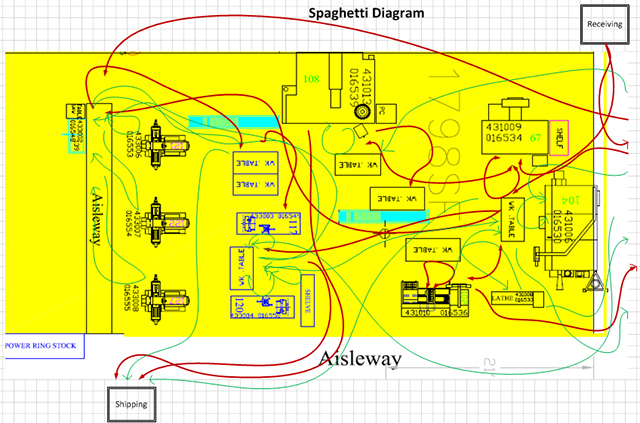
In a Process Layout, similar/identical machines are co-located in functional departments (Manual Lathes, CNC Lathes, Manual Mills, CNC Mills, etc.). Any machine shop that has a Process Layout will always operate in a batch-and-queue production mode! Figure 2 shows the production flow for a sample of 150+ different machined components produced in a CNC machine shop that has a Process Layout. I would hesitate to recommend to any SME to invest in Industry 4.0 if they persist with the worst type of factory layout for HMLV manufacturing!
Implement a Cellular Layout in Shop #1:
First identify the product families in the (Runners + Repeaters) segment of the shop’s product mix. From the ERP system extract the routings of all the parts/products to create the initial Product-Process Matrix. An example of an initial Product-Process Matrix is shown in Figure 3(a). Next, use any commercially available data analysis package like Minitab, SPSS or JMP to manipulate this matrix to get the final Product-Process Matrix shown in Figure 3(b). In Figure 3(b), each family of parts has routings that contain the same (or similar) machines. Each part/product family suggests the group of machines that must be co-located in a manufacturing cell to produce those parts.
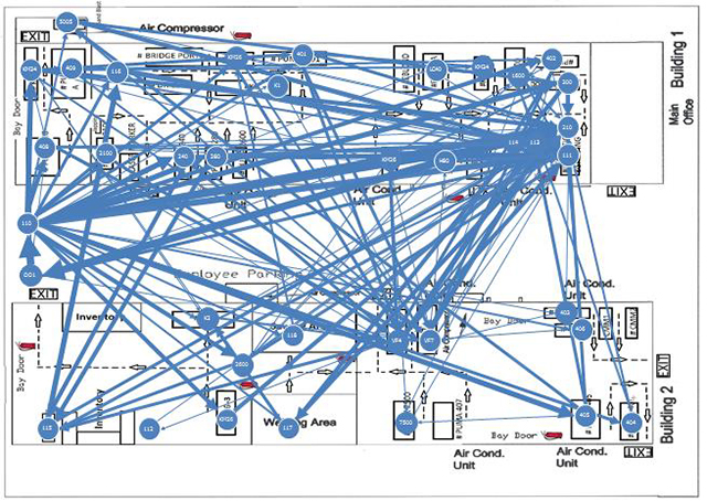
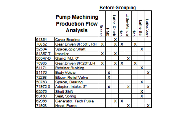 Figure 3(a) Initial Product-Process Matrix before Grouping to Identify Part Families
(Source: http://www.strategosinc.com/gt-production_flow_analysis.htm)
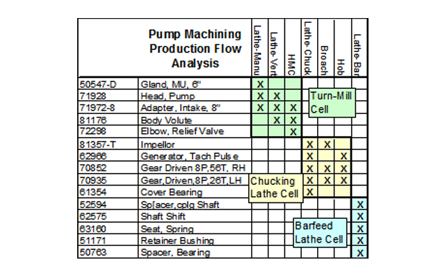
Figure 3(b) Final Product-Process Matrix after Grouping to Identify Part Families
(Source: http://www.strategosinc.com/gt-production_flow_analysis.htm)
Exploit the cellular layout of the shop floor to foster a culture of teamwork:
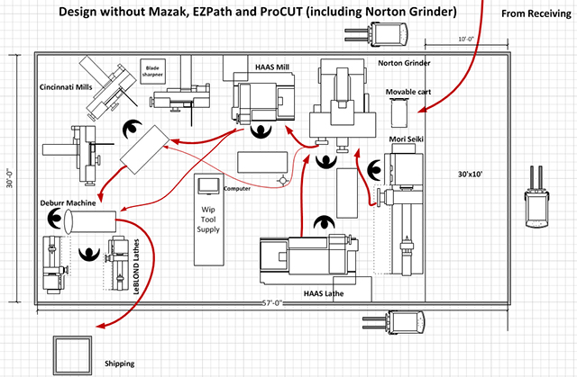
The key to successful implementation of a cell is to co-locate all its machines, personnel and support services in one area. Figure 4(a) and Figure 4(b) display the material flows for the part family that was being produced in a machining cell before and after re-layout, respectively. If a cell is implemented with management’s support, it will (1) have manufacturing focus, (2) retain operational flexibility bounded by the parametric limits of a part family, (3) foster a culture of Continuous Improvement within a group of employees that accepts performance metrics that do not promote selfish, individualistic and elitist behavior, (4) promote a sense of ownership and (5) encourage management to give some level of self-governance and autonomy to its members to help them to complete and ship products to their customers and, what matters most to management, (6) drastically shorten the gemba walks that they take to assess morale and performance of any group of employees.
Right-size non-machining processes to absorb them into the cells:
In general, machine shops are too focused on improving delivery performance and profitability by acquiring multi-million $ metal-cutting machines. In reality, it is the manual machining processes, such as Saws and Drills, the Inspection department and non-machining processes, such as heat treatment, electro-plating, coating, washing/cleaning, etc. that are often the root cause for their long delivery times!
Right-sizing a process that is currently external to a cell, such as Washing, Painting, Deburring, Inspection, etc. would allow it to be brought into the cell. This will have a significant impact on quality, delivery time and work-in-process! Also, it would improve the morale and job satisfaction of the cell personnel. Now, their team’s performance will not be affected by the workmanship and schedule priorities of those who work in other cells and/or external departments whose services are shared by all the cells.
Unfortunately, there are limitations with right-sizing the equipment used in different machine shops. Processes like heat treatment, electro-plating or welding could never be co-located with CNC machines in a cell! Maybe Deburring could be located in a corner of the cell if it was contained within a sound-proofed chamber having a dust collection system. Even affordability of the smaller equipment could be a constraint since a single monument would be replaced by multiple work stations (or machines) given to all the cells whose parts use that process.
Will the day come when the Inspection department in any machine shop can be right-sized and that department is eliminated all-together? The Inspection department, which has zero visual connectivity with the rest of the shop due to its location in a corner of the machine shop, is often the real bottleneck in the shop. Can a CMM (Coordinate Measuring Machine) and other inspection devices be put on a mobile truck that travels around the shop? If that were possible, then inspectors would receive electronic requests from machinists and go to their cells to perform FAI (First Article Inspection). Also, while there is an abundance of Machine Monitoring Systems on the market (www.FactoryWiz.com, www.MemexOEE.com, www.FORCAM.com, www.MachineMetrics.com) that are compatible with all CNC machines, it is unclear if these systems can monitor the “slow poke” Coordinate Measuring Machines that reside in any Inspection department.
Purchase a multi-function machine tool (or a flexible machining system) that combines two or more machines (or replaces an entire multi-machine cell):
It appears that metal removal rates remain the chief driver of a machine shop’s capital investment choices. Unfortunately, this mindset of “keep making chips” results in the purchase of expensive new machines that (1) do not alleviate the shop’s capacity constraints, (2) do not increase throughput at their bottlenecks, (3) waste payroll $ to keep employees busy producing WIP and (4) do not reduce the total distance that the typical order must travel all over the shop. Let us take the case of this family-owned machine shop in Houston that serves several customers in the Oil and Gas industry. The routing for the most complex component they make for a down-hole drilling tool assembly is Saw ![]() Hole Drilling and Boring (Vendor Op)
Hole Drilling and Boring (Vendor Op) ![]() Manual Lathe
Manual Lathe ![]() CNC Lathe
CNC Lathe ![]() CNC Mill
CNC Mill![]() Shaper
Shaper ![]() Inspect
Inspect ![]() Ship. But they make other components that may have a routing like Saw
Ship. But they make other components that may have a routing like Saw![]() Manual Lathe
Manual Lathe ![]() CNC Lathe
CNC Lathe ![]() Inspect
Inspect ![]() Ship or a routing like Saw
Ship or a routing like Saw ![]() CNC Lathe
CNC Lathe ![]() CNC Mill
CNC Mill ![]() Inspect
Inspect ![]() Ship. Should this small family-owned machine shop buy a new CNC Lathe with higher metal removal rates so the Manual Lathes department can be eliminated? Or should it buy a multi-function machining center that combines the operations done on the CNC Lathe and CNC Mill? Or should it explore how to eliminate the Shapers by using their CNC mills to cut the internal splines on some of their parts? Having observed the WIP in the three buildings that comprise this machine shop, the CNC Lathes department is not the shop’s bottleneck. Plus they have a classic Process Layout! So the purchase of a high-priced CNC Lathe with a faster metal removal rate and in-cut spindle time was not going to reduce their WIP nor help them to quote shorter Lead Times. Guess what ths small machine shop’s management team eventually did to drastically reduce delivery times? They (1) eliminated the Manual Turning department by moving their work to the larger CNC Lathes and (2) re-organized the shop into 3 cells as follows: (Cell #1) CNC Turning, (Cell #2) CNC Turning
Ship. Should this small family-owned machine shop buy a new CNC Lathe with higher metal removal rates so the Manual Lathes department can be eliminated? Or should it buy a multi-function machining center that combines the operations done on the CNC Lathe and CNC Mill? Or should it explore how to eliminate the Shapers by using their CNC mills to cut the internal splines on some of their parts? Having observed the WIP in the three buildings that comprise this machine shop, the CNC Lathes department is not the shop’s bottleneck. Plus they have a classic Process Layout! So the purchase of a high-priced CNC Lathe with a faster metal removal rate and in-cut spindle time was not going to reduce their WIP nor help them to quote shorter Lead Times. Guess what ths small machine shop’s management team eventually did to drastically reduce delivery times? They (1) eliminated the Manual Turning department by moving their work to the larger CNC Lathes and (2) re-organized the shop into 3 cells as follows: (Cell #1) CNC Turning, (Cell #2) CNC Turning ![]() CNC Milling, (Cell #3) CNC Turning
CNC Milling, (Cell #3) CNC Turning ![]() CNC Milling
CNC Milling ![]() Spline Cutting!
Spline Cutting!
Instead of their prevailing fixation with metal removal rates and machine utilization, machine shops should buy multi-function machines and systems that combine consecutive operations currently being done on different machines. Especially if those machines are currently located in separate departments, such as CNC Lathes and CNC Mills! By combining machines, the significant delays due to (1) material handling between several machines, (2) waiting for material handlers to pick up and move a batch of parts from one machine to another, (3) batch-and-queue production flow, (4) setup and gauging at every machine, (5) waiting in queue at machines that are shared by multiple part families, etc. are reduced. For example, in the case of the family-owned machine shop discussed earlier, given the many pallets loaded with turned parts received from the CNC Lathes, I tried to impress upon their GM to limit new orders released to that department every day. This is what I told the GM of that shop, “Are you in the business of keeping your lathe operators busy making parts? Or should you focus on completing and shipping as many parts as you can every day?”
How could a machine shop make a major investment to upgrade equipment on their shop floor by buying a new machine or system that reduces material flow? By reducing the number of separate machines in the cell that currently produces a family of parts. The machine shop should first do a Product-Process Matrix Analysis of their product mix to find their part families. For a particular part family, draw a material flow map and compute workloads on the different machines in that cell. Now, identify a set of 2 or 3 machines that perform consecutive operations that appear in the routings of most parts in the family. Next, for all those operations that would have to be done on a single machine, prepare the list of specifications (work envelope, axes of freedom, number of tools, in-process gauging, etc.). Finally, present that list of specifications to the different machine tool vendors who could build the multi-function machine (or system).
“Raze” and standardize the routings of all the parts within a part family:
Every effort should be made to critique and re-engineer the routings of all the parts that have been grouped into a part family based on their similar (or identical) routings. First, the routings should be standardized by eliminating the differences in the machines used and the sequences in which the machines are used. Next, the routings should be standardized by eliminating the differences in the fixtures, tools, gauges, etc. used. I am currently doing research to replace the Process Layout of any job shop with a Hybrid Flexible Flow Shop. Thereby, instead of the Spaghetti Diagram seen in Figure 2, if viewed from the roof of the shop, the material flow of each and every job, regardless of the sequence of machines in its routing, will be linear assembly line-like from one end of the shop to the other.
Instead of the Make-To-Stock approach for Pull Scheduling, use a Make-To-Order approach for Pull Scheduling:
A machine shop typically executes a different schedule every day. Each day’s schedule could have a different mix of jobs, the due dates of the jobs could be different, the lot sizes of the jobs could be different, the number of operations could vary significantly across the different routings, the setup times and run times associated with the operations in the different routings will surely be different, etc. Regardless of all these differences, it is important that the shop receive a feasible schedule every day that loads all the work centers with jobs whose workload does not exceed available capacity constraints on key resources (machines, labor, materials, dies, etc.).
If a machine shop desires to do daily Work Order Releases that will not exceed resource capacity constraints, they should not expect their ERP (Enterprise Resource Planning) system to do this. The typical ERP system uses an MRP (Material Requirements Planning) or MRP-II (Manufacturing Resources Planning) engine to plan production and schedule operations. MRP assumes infinite capacity, fixed lead times, batch production to reduce setup times, etc. Instead of relying on an ERP system, the logical alternative is to use commercial FCS (Finite Capacity Schedulers) like ORTEMS, Opcenter, Tactic or Schedlyzer. It is infeasible to manually decide the set of jobs to release into a machine shop every day after taking into consideration resource capacity constraints, material shortages, changes in vendor deliveries, machine breakdowns, due dates, etc.
In the case of a manufacturing cell, there may not even be a need for scheduling software! Ideally, all of the machines needed to produce any part in its part family (except vendor operations or external monuments like heat treat) should be co-located inside the cell. At the daily morning huddle, the cell’s team could meet with the production controller. They could eyeball the jobs in process or in queue from the previous day and determine if the cell’s bottleneck could process any new jobs if they were released to the cell that day. A cell guarantees start-to-finish control of the flow of its orders within a small area of the shop. So, except for unforeseen emergencies, they can execute as a team to easily ensure on-time completion of all jobs by their due dates. Never underestimate the do-or-die determination of a cell’s team to deliver customer service by completing orders at the right time with the right quality at (or below) cost!
Utilize Water Spiders to manage all shop floor logistics related to executing the daily schedule:
Assume that after their ERP system is integrated with a commercial FCS, a machine shop can generate a feasible daily schedule for each cell, external monuments that are shared by the cells and support departments (Receiving, Shipping, Inspection, etc.). Next they must release that schedule to the shop floor, execute it and, at the end of each shift, publish the current shop floor status of all active jobs to their ERP. The role of schedule execution and status updating in the ERP is fulfilled by an MES (Manufacturing Execution System). There is merit in implementing a fully-integrated system (A success story reported in the open literature at the company where I used to work is available at http://www.lean-scheduling.com/LSI_Case_Studies_Hoerbiger.html and http://www.preactor.com/Company/News-Articles/Preactor-and-Factory-Viewer-Get-Seal-Of-Approval-F#.Wd4N5VtSy1s.) comprised of an ERP (SAP), a Finite Capacity Scheduler (Preactor) and an MES (Factory Viewer) if the facility is large (> 100,000 sq. ft.). However, in the case of a single-location high-mix low-volume machine shop, especially a small family-owned job shop, it may not be advisable to immediately purchase an MES to complement the FCS that took over scheduling from their ERP system. Instead, I advise these smaller machine shops to create the position of Water Spider(s) by freeing up one or more employees on the current payroll. Imagine a job that combines the work that is typically done by a material handler (who reports to the Plant Manager) and an expeditor (who reports to the Production Controller). Specifically, the Water Spider(s) will handle all shop floor logistics related to moving raw materials, in-process batches and finished parts between machines as specified in the routers of the different parts. By virtue of being all over the shop floor, the Water Spider(s) have the “situational awareness” and authority needed to execute, monitor and update the daily schedule that was released to the floor. In a recent JobshopLean implementation project2, the two Water Spiders eliminated the previous practice where every employee (yes, including the skilled CNC machinists too!) was responsible for moving the pair of screws that they finished from their machine to the next machine. The typical process for moving a batch from one machine to the next involved (1) walking across the shop to fetch the bridge crane and docking it at their machine, (2) walking around the shop to find a cart on which the screws would be loaded, (3) returning to the machine to unload the screws off their machine onto the cart, (4) pushing the cart to the next machine and (5) returning empty-handed to their machine to wait for their next job. Significant savings were realized by this machine shop after they consolidated the non-value added walking time of all their shop employees (aka Waste of Operator Motion) into the work done by just the two Water Spider(s)!
Implement a Machine Monitoring System to maximize TEEP (Total Effective Equipment Performance) of those work centers that are the shop’s bottleneck(s):
The Goal is a book (and a video based on it) by Dr. Eliyahu Goldratt that introduces his Theory Of Constraints (TOC). A cornerstone of this theory is the idiom “A chain is no stronger than its weakest link”. In the case of a machining cell that produces orders on-demand for different parts in a part family, the cell can only complete as many orders as the cell’s constraint machine (aka bottleneck) can complete. The cell’s bottleneck is that machine which is always having orders in queue (WIP) during each shift while the other machines remain idle. Dr. Goldratt proposed a 5-step Process Of Ongoing Improvement (POOGI) whose first step is to Exploit the Constraint in the cell (or the entire machine shop). The focus of this step in the POOGI is to “win back” all the avoidable losses of capacity such as setup time, idle time due to non-arrival of the next job, machine stoppages due to CNC program errors, unscheduled breaks taken by the operator, time to change broken tools, etc. (Ideally, POOGI is best implemented by using the Lean tool of Value Stream Mapping where a single map helps to identify the wastes, delays and inconsistencies in the material and information flows for a single product.)
With the abundance of Machine Monitoring Systems on the market (FactoryWiz, Memex, FORCAM, MachineMetrics), it is possible to do 24/7 monitoring of (1) at least the bottleneck machine(s) in all the cells and (This article — Danford, M. (2017, July). Lean Manufacturing Begins with Layout, Commitment. Modern Machine Shop, 78-86 — describes the work that we did at Wear Technology, a CNC machine shop located in McPherson, KS. The article is available online at http://www.mmsonline.com/articles/lean-manufacturing-layout-relies-on-people.) the monuments in the machine shop. Figure 5(a) shows an example of one of the many reports from an MMS that summarizes the capacity losses on a CNC machine. Do you notice that “No Operator” is one of the top three reasons for capacity loss for this particular machine? In contrast, traditional methods such as video monitoring or random visits by supervisors project a lack of trust on the part of management. Plus such reports can be used to conduct a series of kaizens with the sole purpose of improving value-added utilization of those machines (or multi-machine work centers) in the machine shop that are key to increasing its daily order completion performance!
Figure 5(b) presents a systematic description of the four categories into which the time recorded by the MMS for different activities performed on any machine during an 8-hour shift can be categorised. TEEP (Total Effective Equipment Performance) is a performance metric that provides insights as to the true capacity of any manufacturing operation. It takes into account both Equipment Losses (as measured by Overall Equipment Effectiveness) and Schedule Losses (as measured by Machine Utilization). TEEP = OEE X Machine Utilization = Availability X Performance X Quality X Utilization. It is desirable that the TEEP for a cell’s bottleneck be around 80% – 85%. It is not surprising that the Machine Monitoring Systems are aggressively advertised for supporting effective maintenance programs for individual machines or multi-machine cells.
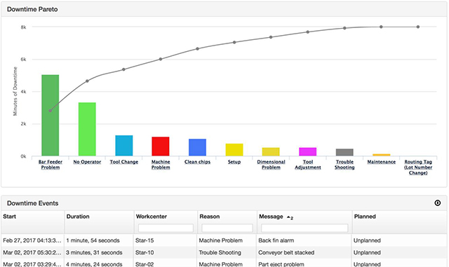
Figure 5(a) Pareto Plot of Capacity Loss Categories
(Source: MachineMetrics)
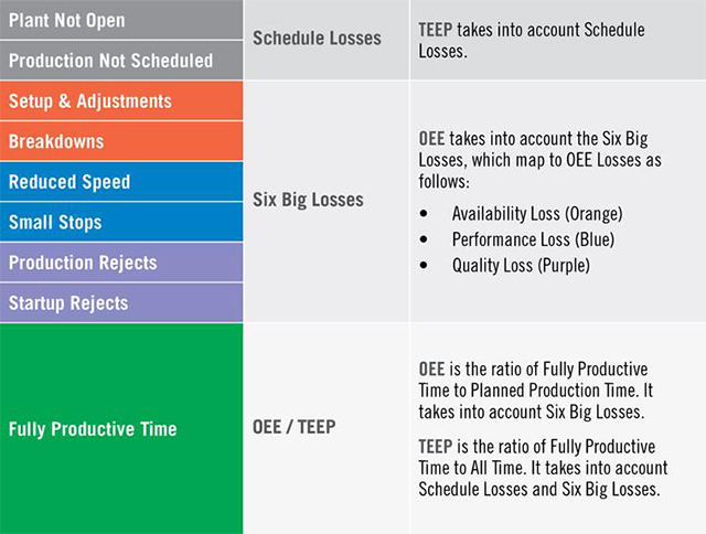
Figure 5(b) Components of the 8 Hours of Theoretical Available Capacity on Any Machine
(Source: https://www.oee.com/teep.html)
Become a machine shop that relies on its ERP system to support all problem-solving events, morning huddles, decision-making and shop floor management:
There is a widespread misconception that limits US machine shops from gaining additional benefits from Lean. It is that Lean and ERP are incompatible! The fact is that ERP systems are here to stay whereas the manual paper-and-pencil Lean tools could go away. ERP systems can support Lean in three ways: (1) they have the functions/modules to implement Lean, (2) they have the data to support Lean projects and (3) they can integrate with 3rd party software that implements Lean practices. Unfortunately, the fundamental shortcoming of contemporary ERP systems is that they do not have up-to-date, complete and accurate data. In fact, some ERP systems appear to be at best systems to support Accounting and Customer Relationship Management professionals!
Here are some of the questions that a machine shop’s leadership team should ask their Production Controller to determine if their ERP can support Lean: (1) Can an order be accurately located with a reliable estimate of its completion date? (2) Can the daily schedule be accessed as an electronic Gantt Chart from any shop floor terminal in the shop? (3) Can the Water Spider(s) receive an accurate Daily Dispatch list of orders during a shift? (4) Can the Water Spider(s) communicate in real-time with the office to update the daily schedule in the ERP system? (4) Can the ERP system support daily morning huddles on the shop floor or meetings in the conference room by providing data analytics and reports on demand to support decision-making? (5) Can the ERP system plug-in to third party tools for Digital Visual Management (iObeya or Leankit)?
If You Are an SME, Should Industry 4.0 Be A Priority?
If any SME wishes to answer the above question, I advise them to take my SAT (Situational Awareness Test):
1. Schedule a 5-day kaizen in your conference room.
2. Invite to that event a representative from each department that “touches” any order that you accept, produce and ship.
3. Select any one of the in-process orders that are on the shop floor.
4. Ask the team this question, “Sitting in the conference room, determine (1) the location and status of this order and (2) whether it will ship on time!”
Next, assuming that the team obtains a correct answer after being confined to the conference room for give days, please request me to send you a copy of the Job Shop Lean Assessment Tool. Complete that questionnaire and return it to me. After I have reviewed your answers to my questions in that assessment, I will have for you a definite answer to the above question.
About the Author

Dr. Shahrukh A. Irani, PhD, owns a consulting company, Lean & Flexible, lc, which delivers Job Shop Lean advisory, training and implementation services to high-mix low-volume (HMLV) discrete product manufacturers. In addition, he teaches two graduate courses on Lean in the Department of Industrial Engineering at the University of Houston.
Dr. Irani has authored Job Shop Lean: An Industrial Engineering Approach to Implementing Lean in High-Mix Low-Volume Production Systems (2020, Productivity Press). In addition, he has edited the Handbook of Cellular Manufacturing Systems (1999, John Wiley).
From 2012-2014, Dr. Irani worked as the Director of IE Research at Hoerbiger Corporation of America, Inc. (HCA). In that position, he gained invaluable industry experience by implementing Job Shop Lean to transform HCA’s high-mix low-volume (HMLV) manufacturing facility located on Milby Street, Houston, TX.
From 1996-2012, Dr. Irani was an Associate Professor in the Department of Integrated Systems Engineering at The Ohio State University (OSU). His research at OSU produced (1) the Job Shop Lean approach to adapt Lean for high-mix, low-volume (HMLV) small and medium enterprises (SME) and (2) the PFAST (Production Flow Analysis and Simplification Toolkit) software that facilitates the implementation of Job Shop Lean. Prior to this faculty position, after obtaining his PhD in Industrial Engineering from Penn State in1990, Dr. Irani was an Assistant Professor in the Department of Mechanical Engineering at the University of Minnesota from 1990-1996.
Dr. Shahrukh A. Irani can be contacted at :


